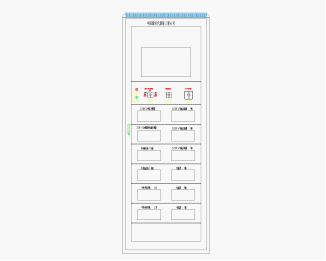
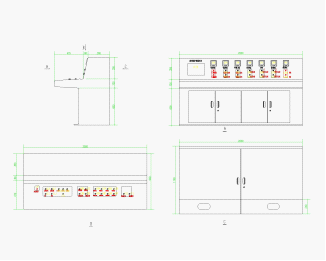
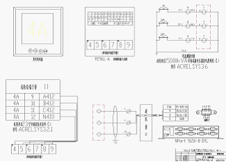
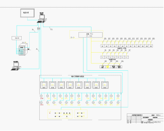
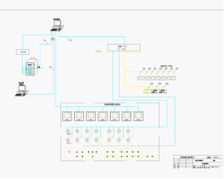
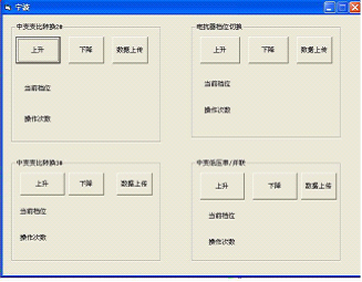
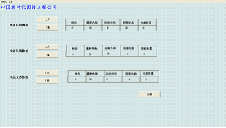
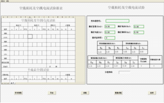
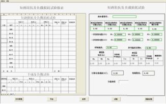
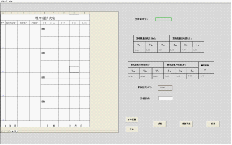
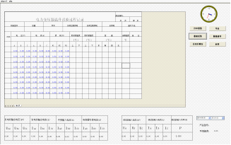
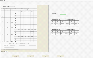
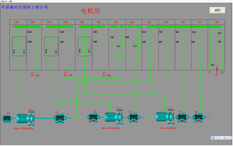
Ankerui  Qing Qing Jiangsu Ankerui Electric Appliance Manufacturing Co., Ltd. Jiangyin , Jiangsu 214405 Abstract: Acrel UHV system, through the days Harbin Transformer Company test circuit monitoring system has two automatic and manual test circuit, can fully guarantee the fault when a certain point, and does not affect the normal operation of the experimental work The main control loop consists of a wiring diagram, a wiring diagram of the motor room, and the interface of each test report. Key words: PLC ; 550KV ; no-load test; temperature rise test; 0 Overview Harbin Transformer Co., Ltd. was founded in 1955 and is one of the 500 largest electrical machinery and equipment manufacturers in China. In the early 1970s, it was designated by the country as a designated factory for the production of 110kV-class power transformer products. In 1992, it was identified as a national 220kV-grade power transformer fixed-point production plant. In 1997, it was identified as the approved unit for the transformation of urban and rural power grids. It is currently the national transformer industry. The key enterprises and leading enterprises in the transformer industry in Heilongjiang Province are mainly engaged in the manufacture and operation of power transmission and transformation equipment, providing customers with power transmission and transformation equipment and integrated solutions and professional services . Anke Rui Electric Co., Ltd. in June 2009 to undertake Harbin transformer limited liability company by the Harbin municipal government invested 700 million yuan carefully build the "double million" Project 220 kV and 500kV EHV transformer plant construction in the automatic control system . 1 customer needs The test system requires that a routine test of a real power transformer with a capacity of 500 kV/720 MVA and below must be completed and that the test system must complete a transformer product test project. The specific contents are as follows: 1 .1 No-load Current and No-load Loss Measurement 1 .2 No-load Current Harmonic Measurement 1 .3 external induction pressure test 1 .4 Short-circuit impedance and load loss measurements 1 .5 Three-phase transformer zero-sequence impedance measurement 1.6 Test temperature 2 main items 2.1 industrial control computer: frequency 2.0, 2G 2 * 500G hard disk memory, a liquid crystal display 22, a printer, a laser A3 2 .2 UPS power supply 2kVA online 2. 3 PLC control cabinet and control cabinet (800 × 800 × 2200) of each stage 1, as shown in FIG. 1 Figure 1 . Table 24 Test characteristic table 2000 * 900 (mm) shown in FIG. 2 as follows: Figure 2 . 25 units, an intermediate transformer indicating instrument operating parameters, monitoring instruments, the specific design shown in Figures 3 and 4 the following drawings; Figure 3 Figure 4 The entire system control software 26 required, the soft index interface shown in Figure 5: Figure 5 . 2 7 500KV 220KV and the control system configuration shown in FIG. 6, 7: Figure 6 Figure 7 3 control of the main equipment 3.1 15000kVA power frequency generator control; 3 .2 7500kVA generator frequency control (220kV test hall Experimental Station UHP common, but not both); 3 .3 2000kVA IF generator control (220kV test hall Experimental Station UHP common, but not both); 3 .4 2000kVA transformer control support; 3 .5 15000kVA transformer control center, shown in Figure 8: Figure 8 3.6 Main control circuit current measurement, voltage transformer, shown in Figure 9: Figure 9 3 .7 900kvar-1800kvar-2700kvar unloaded adjustable compensating reactor control; 4 test items According to the transformer test voltage being tested, the voltage tapping of the intermediate transformer is adjusted, the tap position of the tap changer is displayed, the voltage range of the voltage transformer is determined and adjusted, the gear position and ratio of the voltage transformer are displayed, and the current is determined and adjusted according to the size of the tested current. Current transformer gear position, display current transformer gear ratio and ratio; and ensure that the transformer is not open twice; confirm the position of the isolation knife and determine whether it is correct. The overvoltage and overcurrent values ​​are determined based on the test voltage and current and protected. (The general voltage does not exceed 105% and the current does not exceed 120%). Control the 148kV test output bus's isolation knife position and the correct position. The prompting of the miscellaneous and inconsistent position switches is prompted, and the next operation is not performed until the errors are corrected. a. No-load test b. Load test c. Induction pressure test The above three items are the most basic functions. The test measurement and control system is equipped with automatic segmentation fast and non-oscillating rise and fall voltage, the best current range automatic selection switching function module and advanced generator excitation adjustment equipment. The system should have fast test speed and test data. Accuracy, automatic recording and analysis of various performance data and real-time display of test results and other test results. The system is equipped with manual “slow-upâ€, “slow-downâ€, “fast-risingâ€, and “fast-falling†pressure-adjusting buttons (if the generator has this function) operated by a mouse or keyboard lift key for users to use when manually adjusting the pressure. . Manually adjust the pressure, you can manually click the "data acquisition button" with the mouse at any time to synchronously collect real-time data such as the average value of the three-phase voltage, the root mean square value, the three-phase average current, the total loss of the sample, and repeat the acquisition without limit until The tester was satisfied with the data. 4.1 No-load test No-load test by the computer to call out product parameters according to the product serial number or by the tester to determine the test voltage, adjust the intermediate transformer and confirm, adjust the voltage transformer gear and confirm, adjust the current transformer gear and confirm. Operate each switch and judge whether the position is correct, switch each switch in turn and verify whether it is closed, control the step-up of the generator, control the speed of boosting and the position of the measuring point, and adjust automatically or manually to make the position of the measuring point mean voltmeter The accuracy is less than 0.2% (power analyzer error guarantee) (or the default setting, this data is open to the user, the user can freely set the size), when the voltage is within the error range , the system automatically tests, according to the average voltage Calibrate the no-load loss value and automatically save the data as shown in Fig . 10. Lower the voltage, turn off each switch and confirm in sequence, and the test ends. Figure 10 The tester may adjust the test duration according to the situation so as to observe the condition of the test product. In the no-load test, over-current, over-voltage, and voltage unbalance protection are set according to the transformer under test, and the value during operation is locked during the protection action to analyze the nature of the fault. 4 .2 Load loss test The load loss test can be used by the computer to call up the product parameters according to the product serial number or the tester can determine the test current and test voltage, adjust the intermediate transformer, adjust the voltage transformer gear position and confirm, adjust the current transformer gear position and confirm. Operate each knife gate and judge whether the position is correct, combine each switch in turn and verify whether it is closed, control the generator boost pressure, control the boosting speed and the measuring point position, and can automatically or manually adjust, when the current is within the error range, The system automatically tests and automatically saves the data as shown in Fig . 11. The voltage is reduced, and the switches are turned off and confirmed one by one. The test is completed. Figure 11 The tester may adjust the test duration according to the situation so as to observe the condition of the test product. The load loss test can be performed directly on the rated tap, maximum tap and minimum tap (or tap determined by the tester), and the data can be saved in the database in sequence. In the load test, overcurrent, overvoltage, voltage unbalance, current unbalance, etc. are set according to the transformer under test, and the values ​​during operation are locked during the protection action in order to analyze the nature of the fault. 4.3 induction voltage test Induced withstand voltage test by the computer to call the product parameters according to the product serial number or by the tester to determine the test voltage and test time, adjust the intermediate transformer gear and confirm, adjust the voltage transformer gear and confirm, determine the test current, adjust the current transformer file And confirm. Check the position of each switch and judge whether it is correct, switch each switch in turn and verify whether it is closed, control the step-up of generator, control the speed of boosting and the position of measuring point, and adjust automatically or manually to make the position of measurement point more than 97% , less than 101% (or the default setting, this data value is open to the user, the user can freely set the size), the system automatically time, the end of the timer, reduce the voltage, turn off each switch and confirm , as shown in Figure 12: Figure 12 The tester may adjust the test duration according to the situation so as to observe the condition of the test product. In the induced voltage test, overcurrent, overvoltage, voltage unbalance, current unbalance, etc. are set according to the transformer under test, and the value during operation is locked during the protection action to analyze the nature of the fault. 4 .4 Temperature rise test The computer system has an external sample temperature data communication interface and can display standard communication signal data in real time. The above measured data and calculation result data can be archived to the database for query and printing at any time , as shown in Figure 13: Figure 13 Harmonic analysis 4.5: 1 to 19 harmonics, harmonic components and the transformer load loss measurement measuring simultaneously, the measurement of phase current 19 within the three-phase voltage harmonic component, each harmonic can display a list of The percentage of wave component is printed on A4 paper. The above data can be saved for future inquiry. 5 Computer, PLC Network and Control Protection HMI system with 5.1 humane: start of the test to the end, both the system prompts. Test data, test record query and print function: All test data are stored in the system database, can be queried and printed in different ways, such as query by test item number, test date, or in a test sequence by rolling Inquire. The test record format is provided by Harbin Tiantong Transformer Co., Ltd. The system is equipped with software used on computers on the network connected with the main industrial computer of the system, and is used by other terminal computers on the Internet to inquire, print test records, and input other data such as DC resistance and transformation ratio , as shown in FIG. 14 . Figure 14 5.2 system is running, even if the computer crashes, the system is not out of control, the system has an emergency stop button. And the use of reliable isolation measures to prevent high potential into the computer network system, the system should have high reliability. 5.3 a computer system (test bed) can query, display, all major operating data control system, such as the temperature of each point of the unit, over-temperature alarm (if there is this communication function generator), current, voltage, Real-time values ​​of power, power factor, active power, frequency, and other parameters. As shown in Figure 15: Figure 15 5.4 generator control The generator control will perform excitation adjustment, excitation current, and voltage measurement, respectively. Generator output switch control; generator output current and voltage measurement (three-phase simultaneous display including electromagnetic meter on switchgear); generator over-current, over-voltage protection, over-current and over-voltage protection values ​​have default value and input value Ways. The above protection and electromagnetic quick-break protection cooperate with each other in terms of time and protection value, making the protection more perfect and more reliable. The above operations are all done on the computer , as shown in Figure 16: Figure 16 5.5 Police lights, bells, emergency stop button: Alarm lights and bells are controlled by the computer through switch auxiliary contacts. Ensure that the program is correct. Normally, before the power is turned on, three rings of alarms are sounded every 2 seconds. After the power is turned off, an alarm bell rings for 5 seconds. When the safety switch is in the operating position, the warning light is on and the warning light is off after the position is forbidden. The emergency stop button is installed on the main control room and each control box to ensure reliable disconnection of the power circuit in the event of an emergency to ensure personal and equipment safety. 5.6 can be seen following the actual voltage and current A 4, B, C of the three-phase on the computer: Generator set or regulator output voltage and current, three-phase total of six values; test intermediate transformer output voltage and current, three-phase total of six values; (transformer output current transformer); capacitor tower (if They put into use) output voltage and current, three-phase total of six values; (current transformer output terminal has a current transformer); measured by the measuring system to increase the voltage and current on the transformer under test. The voltages on the transformer, capacitor tower, and sample are the same, all from the power analyzer, as shown in Figure 17. Figure 17 6 Conclusion: Adopt PLC programming control system to carry out centralized control on the control part of the whole test station, through complex interlocking and interlocking circuit design, to prevent the occurrence of human misoperation; the PLC programming controller used by the German Siemens production, control components by Schneider provides transformer microcomputer integrated test system designed by China New Era Engineering Co., Ltd., with high-precision imported power analyzers and other measuring instruments, which can measure, collect, display, and store data; PLC control cabinets and monitoring systems are used. Optical fiber communication; the test station can complete the selection of test power through high-voltage isolation switch, and at the same time, control power of the test power can be controlled by the test bench; as the two laboratories share two sets of test power. Wiring is more complicated. In order to ensure equipment and personal safety, each test stand is set up with electrical interlocks. At the same time, the analog operating disk is set in the test room to show the connection status of the test system, so that the test personnel can grasp the overall operation of the equipment. Since the high-pressure test system has been put into operation, it has greatly improved the accuracy of the test data and the data preservation time, provided basic data and basis for the realization of the traceability of the ex-factory transformers, and won praise from the users! Sheet Metal Fabrication Custom,Machining Parts,Sheet Metal Stamping,Sheet Metal Components Shenzhen Bergek Technology Co.,LTD , https://www.szbergek.com


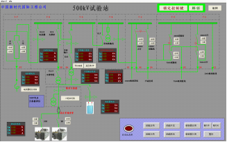
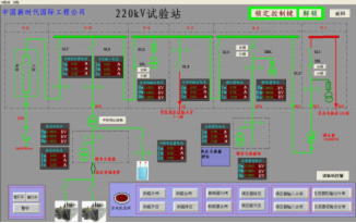

Application of Ancorrit high pressure test system in a UHV manufacturing base of a company in Harbin
Prev Article
Refueling vehicle fire safety related matters