Aluminum Ferrule,Aluminium Ferrules For Wire Rope,Aluminium Ferrule For Crimping Wire Rope,Aluminium Ferrule Wire Rope Jiangsu Ruijin Sling Co.,Ltd. , https://www.cnsteelcable.com
2 relay detection program to take the relay to detect circuit breaker fault signal schematic diagram as shown in Figure 1 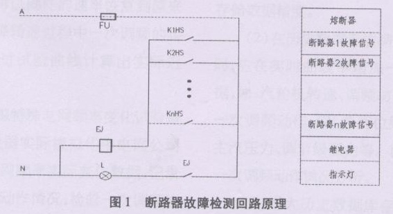
In the above figure, the circuit breaker K1HS-KnHS is a distribution cabinet. When any circuit breaker in the distribution cabinet fails, the auxiliary contact breaker K1~Kn breaks the alarm auxiliary contact. Closed, when the relay EJ closed, so that through the installation of the indicator L alarm, in addition to the relay EJ output signal sent to the unit distributed control system alarm.
The advantages of this scheme are simple, easy to implement, and low cost; the disadvantage is that only the faults of the entire set of circuit breakers can be judged, and it is impossible to directly determine which one of the circuit breakers is faulty, and it needs to be viewed and judged on the ship side.
3 Switching measurement front-end detection scheme In order to directly determine which circuit breaker is faulty, the circuit breaker fault breaking alarm signal needs to be connected to the unit distributed control system respectively. There are two methods: one is a hard-wired direct-to-unit distributed control system ( DCS), but will lead to an increase in the number of I/O points and cables of the unit's decentralized control system; the other is to draw on the idea of ​​DCS remote I/O of the unit, and set up a switch-measure front-end in the power distribution cabinet. K1HS~KnHS's broken array alarm auxiliary contact is directly connected to the switch quantity measurement front-end. Each switch quantity measurement front-end is interconnected and communicates with the unit's decentralized control system. The communication connection with the unit decentralized control system is shown in Figure 2: 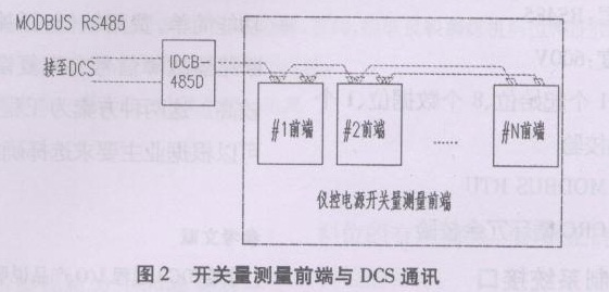
This scheme is convenient for directly determining the failure of a circuit breaker and has strong functions, but the cost is relatively low and it is more complicated to implement.
4 switch measurement front-end features (1) true dual-bus network dual-serial measurement front-end, constitute the network after the two buses can communicate at the same time without affecting each other, two networks can use different baud rates and protocols, but also at the same time Connecting to two different systems is a true dual-bus network.
(2) Strong openness Adopts fieldbus technology. It has good openness. The communication protocol is completely open and open. It is very easy to network with other systems, especially DCS.
(3) On-site display and configuration with LED indication, used to indicate the front-end work and communication status, used to display measurement and configuration data, convenient for debugging and maintenance, and on-site configuration.
(4) Network redundancy provides dual-network redundancy and is a true redundant interface. Each front-end CPU has two UARTs that can work at the same time. The two buses can work in parallel at the same time, greatly improving the reliability of the bus-type network.
(5) The balanced differential transmission method adopted for high anti-interference ability and environmental adaptability and the box structure designed for the harsh environment of industrial environment have very strong environmental adaptability and anti-jamming capability.
5 Switch Measurement Front-End Network Specifications Index Number of Hosts: 1-2 Front-End Addresses are Defined in Range of ~255
Main station type: DCS, IPC, compatible, notebook, laptop, number of connected stations (that is, the number of front-ends that can be attached to a network): ≤ 50
Network topology: linear bus, long-distance two-resonant terminator (matching resistor), stub ≤ 0.3m, no branch.
Transmission medium: shielded twisted pair communication rate: 9.6k, 19.2k, 38.4k, 115.2k The basic communication distance can be set: 1.2km
Network Communication: Half duplex asynchronous communication physical layer: RS485
Network isolation: 600V
Data format start bit, 8 data bits, 1 stop bit, no parity communication protocol: MODBUSRTU
Communication Verification: CRC Cyclic Redundancy Check 6 Interface with Distributed Control System Communication: Half duplex asynchronous communication port Model: RS485
Communication Protocol: MODBUSRTU
Master-slave relationship: DCS is the main station, and the remote I/O front end is the slave station. Communication rate: 9.6k, 19.2k, 38.4k, 115.2k The data format can be set: start bit 1/data bit 8/stop bit 1 / No parity 7 Summary Relay detection circuit breaker fault signal program is simple, simple, and low cost; switching measurement front-end circuit breaker fault signal detection scheme is complex, powerful, and costly. These two schemes provide a reference for engineering design, and can be selected according to the requirements of the owners.
Introduction of Test Signal Design Scheme for Circuit Breaker Circuit Breaker
1 Overview Instrument control power supply includes AC 380V power supply, AC 220V power supply, DC 220V (110V) power supply, DC 48V power supply, and DC 24V power supply, etc. It is an important basis for ensuring the safe and normal operation of the instrument and control equipment. The instrument control power supply shall be obtained from the factory low-voltage power distribution device or DC network, and the instrument control equipment such as electric gates, solenoid valves, and meters shall be provided and constitute an independent distribution circuit. The distribution circuit shall be provided with a circuit breaker and the circuit breaker shall be configured. Circuit breaker overload, short circuit action will change the fault signal contact. In order to monitor circuit breaker faults, two design schemes for detecting fault signals of the circuit breaker at the front end of relays and digital measurement relays are described below.