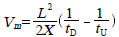
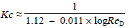
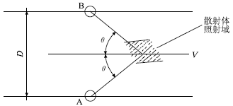
The Ultrasonic Flowmeter is a meter that measures the volumetric flow rate by detecting the effect of ultrasonic waves (ultrasonic pulses) on fluid flow. Ultrasonic flowmeter has the following main characteristics: no component is inserted in the fluid to be measured, no effect on the flow rate, no pressure loss; can be used in any liquid, especially liquids with high viscosity, strong corrosion, non-conductive properties The flow measurement can also measure the flow of gas. For the flow measurement of large-diameter pipes, the investment will not increase due to the large pipe diameter; the range is relatively wide, up to 5:1; and the output and flow are linear. Due to these unique advantages, the development of ultrasonic flowmeters has been very rapid, and has become one of the commonly used flowmeters. Its application field is expanding and has a very good development prospect. Ultrasonic flow meter detection principle includes two kinds: time difference method and Doppler method. At present, the most commonly used ultrasonic flowmeter on the market is the time difference ultrasonic flowmeter. Doppler ultrasonic flowmeters have certain limitations due to their high requirements for measured media. The following describes the detection principle and selection application of the two ultrasonic flowmeters. 1 The principle of time difference ultrasonic flowmeter As shown in FIG. 1, a schematic diagram of a pipeline-mounted ultrasonic flowmeter measurement can clearly show the simplified geometric relationship of ultrasonic wave propagation in the pipeline between the sensor probes A and B. Among them, the angle between the ultrasonic propagation channel and the axis of the pipeline is β, and the diameter is D. Ultrasound passes through the pipeline like a ferry crossing a river. If there is no fluid flow in the pipeline, ultrasonic waves will propagate in both directions at the same speed. When the fluid velocity in the pipeline is not zero, the ultrasonic waves traveling downstream in the direction of flow will speed up and the ultrasonic waves propagating upstream will become slower. Thus, with respect to the absence of fluid flow, when there is fluid flow in the pipeline, the time tD for downstream propagation will be shortened and the time tU for countercurrent propagation will increase. Based on the difference in the two propagation times, the fluid velocity in the pipe can be calculated. This is the basic measurement principle of the time difference ultrasonic flowmeter. Fig.1 Time-difference ultrasonic flowmeter measurement In Figure 1, the following relationship holds: Combining equations (1) and (2) above and solving it, you can get: In the formula, the length of the propagation path between the L-ultrasonics and the stills, m; The projection length of X-channel length on the parallel line of the tube axis, m; tD, tU—ultrasonic propagation time and countercurrent propagation time, s; C—speed of propagation of ultrasound in a stationary fluid, m/s; Vm—average flow rate over the channel between the transducer and the transducer, m/s. Actually, the flow rate calculated in Equation (3) is only the average of the velocity of the fluid in the sound propagation direction. What the user wants to know is the average flow velocity V across the pipe cross-section. Calculating V from Vm generally introduces a velocity distribution calibration coefficient Kc, which can be obtained by: V=KcVm (4) The average flow velocity in the V-pipe cross section, m/s; Vm—average flow rate over the channel between the transducer and the transducer, m/s. Kc—calibration coefficient of velocity distribution. The value of Kc depends mainly on the Reynolds number of the fluid. If the vocal tract is in the plane passing through the axis of the tube, then an approximate value of Kc is given by (5): The ReD-fluid Reynolds number in the formula; For well-developed turbulence, if the vocal tract is not in the plane passing through the axis of the tube (ie, the inclined string), the Kc coefficient and its relationship to the Reynolds number will be different. 2 Doppler ultrasonic flow meter working principle The Doppler (effect) method uses the acoustic Doppler principle to determine the fluid flow. The Doppler effect causes the sound wave to change in frequency when there is relative motion between the sound source and the target. This frequency change is proportional to the relative speed between the moving target and the stationary transmitting transducer. Figure 2 is a schematic of a Doppler flow meter measurement. Fig. 2 Doppler ultrasonic flowmeter measurement As shown in Fig. 2, the sensor probes A and B of the ultrasonic flowmeter are installed outside the pipeline, where A is the transmitting probe and B is the receiving probe. A sends a continuous ultrasonic wave with a frequency of fA to the fluid and scatters particles or bubbles in the liquid in the irradiated region. The scattered ultrasonic wave produces a Doppler shift fd. Probe B receives an ultrasonic wave with a frequency of fB. It can be seen that: The velocity of V-scattering body movement in the formula, m/s; C—speed of propagation of ultrasound in a stationary fluid, m/s; Θ-channel angle. Since the sound velocity of the liquid is about 1500m/s, the measured flow rate is only a few meters per second, that is, C is much larger than V, and thus equation (6) can be simplified as: The Doppler shift fd is proportional to the scatterer flow rate, ie: From equation (8) we can see that Doppler ultrasonic flow meter is used to measure the fluid flow rate in the pipeline through the above principle. Knife Gate Valve,Gate Valve,Knife Valve,Stainless Steel Knife Gate Valve Wuzhong Instrument Co., Ltd. , https://www.wzivalve.com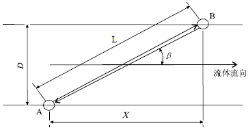
 (1)
(1)  (2)
(2)  (3)
(3)  (5)
(5) 
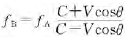 (6)
(6)  (7)
(7) 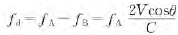 (8)
(8) 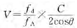 (9)
(9)
Ultrasonic flowmeter application
Next Article
Self-priming pump common faults and solutions
Prev Article
Widespread use of sprinklers