Amphibious Excavator Undercarriage Track Chains Amphibious Track Chain,Cylinder Tightening Chain,Jy Amphibious Excavator Chain,Amphibious Excavator Undercarriage Track Chains Binzhou Jinyi Equipment Co.,Ltd , https://www.jyexcavator.com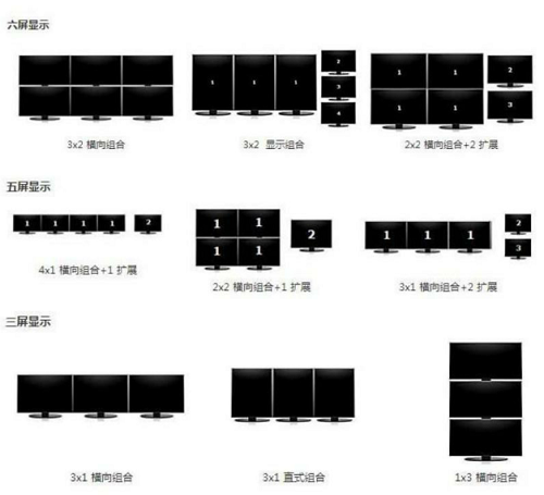
Display terminal <br> <br> Samsung MD230 is equipped with D-Sub, DVI-D and DisoplayPort three video interfaces, two USB ports. Which is equipped with DisoplayPort interface is to support AMDEyefinity multi-screen display technology, which requires the main display must use the DisplayPort interface. 
Supports Eyefinity Technology Graphics
If you want to build Eyefinity multi-screen display system, all displays using the DP interface is the most perfect choice, but the current graphics card with six DP interface is not yet on the market, so the second best method is to use at least one DP interface. , And the rest of the monitors can be connected to the DVI/VGA or HDMI interface on the graphics card. Currently, the HD5000 graphics card in the market only supports the construction of a single card and three screens. 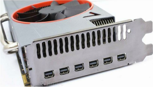
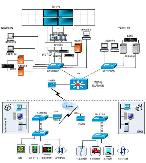
The overall design of the network topology <br> <br>
<br> <br> system configuration diagram of the system in accordance with the master plan Monitoring Center province - level management model system architecture station / tunnel - the road management office. 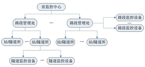
The system adopts the management mode of the road section management office->station/tunnel. The road section management office is responsible for all high-speed (including tunnel) monitoring and management of the area under its jurisdiction, and has all the functions of the tunnel management system, completes the analysis of data collected by the external field equipment, handles abnormal conditions, monitors images, and issues control instructions to reasonably induce traffic flow. As well as the daily operation and maintenance of the system, it also collects, counts, and prints information on the entire line of traffic data. The station/tunnel is responsible for monitoring the tunnels under management, and completes management functions such as tunnel traffic monitoring, ventilation, lighting, firefighting, fire and environmental monitoring.
Data Link Diagram
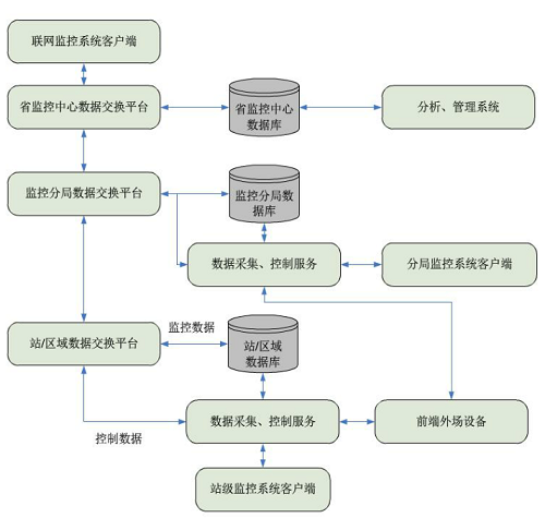
The system uses a unified protocol data exchange platform to achieve monitoring and control information exchange and data sharing synchronization at all levels of the monitoring system. Between the data exchange platforms at all levels: the upper and lower level, level data exchange platform uses a loose connection, and the connection definition is defined in the module link table. As long as the connection between the two data exchange platforms is defined, the two data exchange platforms can exchange data. The provincial central data exchange platform is connected to all monitoring branch office data exchange platforms: the monitoring branch office data exchange platform is connected to all station data exchange platforms in the region. Data exchange uses the principle of the shortest line to achieve the corresponding purpose module through the data exchange platform.
<br> <br> functional block diagram of the system main function is to collect traffic data highway outfield equipment and real-time road data, the data will be collected in the form of analog map-friendly image display; and his vehicle by analyzing real-time data processing Conduct traffic induction. At the same time, the system provides background management functions, which can configure and manage system field equipment, system basic information, and system users. 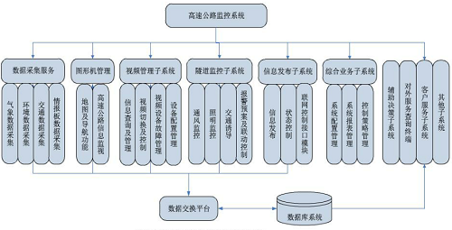
Introduction of Multi-screen Display Scheme for Highway Tunnel Monitoring
Multi-screen display program overview <br> <br> use of current advanced Eyefinity (wide area) technology, multiple high-resolution monitors, perfectly stitched together to expand the desktop computer workspace, combined with comprehensive Xiang build self-developed transportation of highway monitoring system platform, maximize the use of multi-screen mosaic screen display area of ​​the display case equipment all sections real-time, allowing users clear control of highway traffic. It greatly improves the work efficiency of monitoring, management, and dispatching, and also reduces the visual fatigue of related workers and reduces the intensity and pressure of work. Hardware Description <br> <br> build a highway monitoring system based on multi-screen mosaic of hardware required for basic equipment as follows:
Figure: Samsung MD230 display
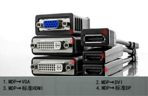
Without DisplayPort monitors using ordinary display means active converter, the display may be DVI-D connector and is connected to the graphics port DP to obtain the effect of the multi-screen output. Figure: 6DisoplayPort interface graphics compatible with 6 screens
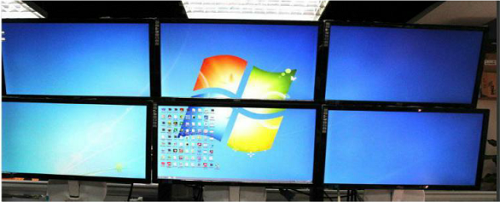
Figure: Multi-display mosaic effect
Figure: Network Monitoring System Network Hardware Architecture Diagram
Figure: System Structure
Figure: Network monitoring system data link structure diagram
Figure: Networking monitoring system functional block diagram