In the design of the connecting rod, more and more dynamic characteristics are studied. The state parameters such as the frequency mode of the flail structure provide the basis for the structural dynamic analysis and subsequent dimension optimization of the connecting rod. 1 Collaborative optimization design environment 0 technology, not only provides a research and development plan for R&D personnel, a new platform. 8, the appearance of 1 also allows the company to comprehensively apply a variety of 0 forgiveness, squatting, product development services become possible, exhibition, is (1) ANSYS solve the actual generation of new products, providing a new platform for the system, to ensure the design It is best to coordinate and analyze the results of simulation analysis and experimentation, so that designers and analysts, Ningwa managers are on a platform. At the same time, the work and communication associations can not only be on the same platform, but also integrate the resources of software, hardware and data, and realize the collaborative development data of different design analysis and test personnel of various departments. The earth has improved the efficiency of research and development of wide-ranging juices and improved the level of bamboo. The original Yiliqiao computer-aided design software 疋, 维dimensional geometric model, the film is saved as the Yang 8 format of the text, in the milk 8, Can 1 integrated environment, through the generation of 3 gamma mode will be 1 levy 8 format file Introduced to the boundary, 1 plus Shen Jian 1 Liandong Dongdong, Wuhan University of Technology, master's degree, the main research direction is finite element simulation analysis and conditions and vibration mode under each mode, analyze the calculation results and point out the connecting rod The weak link. The establishment of the 2-link finite element model When modeling the dimensionality of the solid structure, it is often modeled by the following method, which is suitable for models with relatively simple structures. In dimension 0, the dimension model is built in the software, and the model is imported through the interface with the analysis software, which is suitable for more complex models, but the model is easy to make mistakes after importing, which brings difficulties to the division of the next step mesh, and the repair model needs to be wasted. A lot of time and effort. In the dimension 0, the software establishes the dimension model, using the 0 interface to read in 1 1 or tear 16 mode, 0 can be 61 in 3, this method can correctly import the dimension model, and can directly directly use the ugly platform. The structure plays the grid and performs the corresponding analysis. Dimensional geometric model, and saved as a format file, through which 3 mode is imported to 0. In the grid geometry of the geometric model, the default option of 0 Can 61 is used to divide the connecting rod into 9253 units of 15253 nodes. The finite element model of the connecting rod after the grid is divided. The length direction of the rod is the special axis, and the center line direction of the large round hole of the connecting rod is 7 axes. The finite element solution of the 3 links and the result analysis are the plane movement of the connecting rod, and the two ends are limited by the piston pin and the crank pin. To this end, a cylindrical coordinate system is defined on the axis of the hole at both ends, and the point on the hole end has a degree of freedom of rotation about the axis. The mode is determined by the inherent characteristics of the system and is independent of the external load, so no load boundary condition is required. Using the dimensional finite element model established above, the dynamic characteristics of the air compressor link along the 4 are analyzed, and the cutoff frequency is analyzed by default. The 20th-order mode of the connecting rod is intercepted, and the result is 1. The calculated value of the order 甩2 1 is the calculated value. It can be seen from the calculation results that the modal of the connecting rod is dense and has a first-order mode, while the modes between 2000 and 4100 are mainly distributed at 3400. There is a 7th-order mode in the 4100 band, and the difference between adjacent two-order modes is not very large. The vehicle compressor is in variable working condition, the inertia force of the reciprocating motion of the gas force transmitted by the piston and the inertial force generated by the self-oscillating force during the working process, and the assembly stress generated by the interference of the large and small bearing And the pre-tightening force of the bolt. The change of inertial force is related to the rotational speed of the compressor. The frequency is usually the harmonic of the fundamental frequency of the engine of the compressor. The gas force can be regarded as pulse excitation to some extent, and its frequency range is very wide. 3. Calculated result It can be seen that in the working process, due to the dense mode of the connecting rod, the resonance response is easy to occur, and the dynamic stress of the connecting rod is too large, so that fatigue cracking occurs. In particular, the 12th-order modal frequency is relatively low, and the excitation of the engine in the low frequency band is also large, so it is easy to cause a large vibration mode to reflect the relative value of displacement between various parts of the structure under a certain mode. From the vibration mode, the current shape of the vibration response of the connecting rod in the vibration mode can be found, and the position of the node during the vibration can also be found. In the case of a node, it is also a part that is prone to damage when the structure is dynamically responded. The vibration can reach a linear combination of the natural modes of each order. The low-order natural mode has a greater influence on the vibration of the high-order pair. The lower the order, the greater the influence. Therefore, the low-order mode is connected to the connecting rod. The dynamic characteristics play a decisive role. Therefore, the analysis and calculation of the vibration characteristics of the connecting rod are usually carried out by analyzing the low-order modes. 4 This paper mainly analyzes the 8th-order mode of the connecting rod 1700 and below 2, and the 2 is the connecting rod. 1st order, 8th order vibrating. 0 The first-order mode has a poor mode shape along the axis. The eighth order mode. It can be seen along the 7-axis that in the first 8 modes below 1700, the vibration modes of the connecting rod are various, and the set is the bending vibration. The first order, the second order, and the third order are the two axes of the wrap axis, respectively. The bending vibration is slightly twisted; the fourth order is the local vibration of the small end of the connecting rod; the fifth and sixth order modes are the bending vibration around the 2nd axis and the 1st order 2nd order respectively; the 7th order is The bending and torsion of the connecting rod is 6 vibrations; the 8th order is the 2nd order 3rd order bending vibration around the 2 axes. Under all the full-motion modes, the round hole of the connecting rod has a rounding hole. The rounding of the hole will cause the big head and the crankshaft connecting rod small head and the piston pin to lose normal cooperation, resulting in a common holding tile. A series of failures such as fatigue reduction of the material. The bending vibration of the connecting rod causes the piston to be skewed relative to the bearing sleeve relative to the bearing sleeve, creating additional stresses that cause cracks and damage. It can also be seen from the vibration mode that when the bending vibration and the bending-torsion composite vibration, the structural shape of the connecting rod changes the most, and the node position of the first-order, second-order, third-order bending mode is in the middle of the connecting rod. The node position of the fifth-order bending-torsional vibration mode is basically the same as that of the sixth-order bending mode, and there are two node positions, respectively, in the joint portion of the connecting rod shaft and the connecting rod and the connecting rod shaft and The combination of the big head; the seventh-order bending-torsional composite vibration occurs in the middle of the shaft, stress concentration occurs; the eighth-order bending mode has two nodes, respectively in the middle of the connecting rod and near the small head. Therefore, when designing the connecting rod, it is necessary to consider not only the influence of stress concentration on the joint between the shaft and the size head, but also the influence of the middle part of the shaft and the dynamic characteristics of the connecting rod on its fatigue strength. 4 Conclusion The analysis of the dynamic characteristics of the connecting rod is the supplement and development of the static setting. It is an important means to rationally design the connecting rod structure to improve its reliability. The modality of the connecting rod is dense, especially the first and second order modes. The frequency is low, and the action of the air compressor is excited during the 1st process, which is more likely to cause the resonance response, resulting in excessive dynamic stress in some parts of the connecting rod. The design should be improved to pay attention to the stress set of the connecting rod. However, the stress concentration phenomenon of the shaft is also obvious, which should change the traditional concept of designing ten, in the design, allowing for the middle of the connecting rod. Cracks are easily generated due to bending vibration, so it should be fully considered when setting the juice to avoid excessive bending vibration and reduce fatigue damage to improve the service life of the connecting rod. It is effective to analyze the dynamic characteristics of the connecting rod by the finite element method. 1 Du Jiean, Gan Yuzhong, Yu Yating. Principle of finite element method, service and application Beijing National Defense Industry Press, 2004. 2 small, room. The latest classic milk 8 and 661 this tutorial. Beijing Electronic Industry Press. 2004, Han Songtao, Hao Zhiyong. 4108, finite element analysis of modal characteristics of diesel engine connecting rods. Vehicle and power technology. 2000,43739.
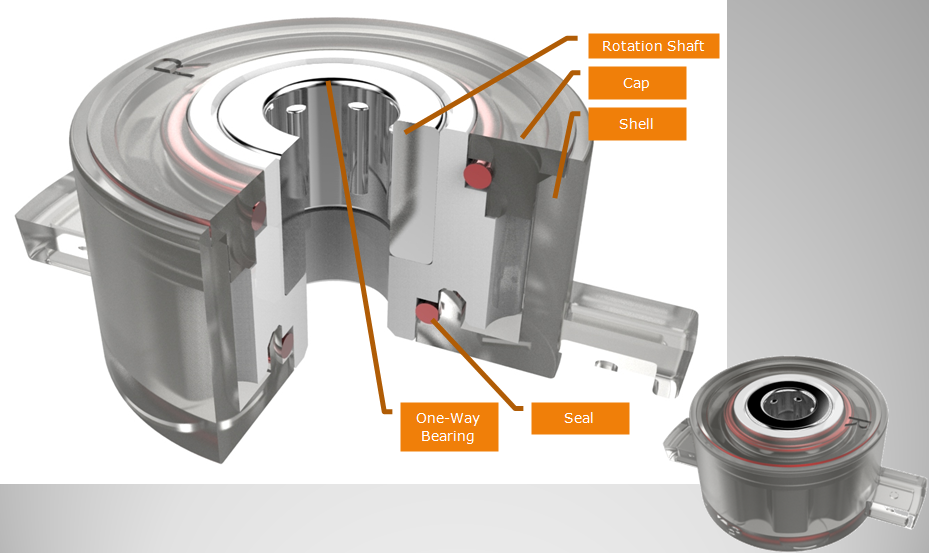
The design of middle through hole is easy to install, Barrel Damper is usually used in small spaces. ABD barrel dampers are the perfect solution for a wide range of applications. Barrel dampers are widely used in automobile interior decoration, household electric appliances, furniture, hidden socket, etc. Our dampers can make the movement of structures soft, quiet and safe to mitigate the impact, avoid the damage, increase the mechanical life, reduce noise, and improve product quality.
NOTE:
1. Please contact the corresponding product
engineer for specific torque products.
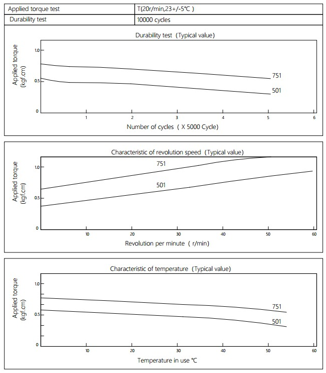
2. Max. rotation speed: 50r/min
3. Max. circle rate: Clockwise180 °, 180 ° anti-clockwise for 1
cycle
4. Operating temperature: -10~50℃
5. Storage temperature:-30~60℃
Applied torque:(T)
Test Temperature:23+/-5℃
Rotating speed:20r/min
Durability test Method:Clockwise 180 °, 180 ° anti-clockwise
Rotating speed:20r/min
Test Frequency:1cycle/min
Test Temperature:23±5℃
Durability test cycle:10000 cycle
Test result criteria: Store in the room temperature for 24 hours or more after the test, recording to the torque T=T±30%T.
Barrel Damper Barrel Damper,Plastic Dampers,Manual Barrel Damper,Toilet Seat Damper,Plastic Barrel Rotary Damper Shenzhen ABD Equipment Co., Ltd. , https://www.abddamper.com

Analysis of Modal Characteristics of Automobile Air Compressor Link Based on AWE